Kestrel Computer Project
Aiming to build a full-stack, open source, and open hardware home computer.
Modular Firmware
06 Dec 2016
Abstract
The Kestrel-3 computer design should be portable to a reasonable number of different FPGA development boards. However, each board offers different hardware resources, interfaces, RAM sizes, and other attributes that directly affects compatbility. Instead of building system firmware images for specific configurations of specific FPGA boards, producing a combinatorial explosion of firmware images which must be maintained and tested, it would be far simpler if we can break things into individual, more easily managed components. This allows for simpler maintenance, but also allows the user to build firmware images without complex or heavy-weight software development tooling.
Introduction
The Kestrel-3 requires, like any computer, some “initial program” in order to run. Unlike the IBM System/360 and DEC PDP-11, I cannot just place a deck of punch cards or a roll of paper tape in a reader to “IPL” the computer. The initial program for the Kestrel-3 must be placed in ROM, or something approximating its behavior. This should come as no surprise to anyone.
However, the Kestrel-3 computer design aims to target at least two different FPGA development boards: the Digilent Nexys-2 (no longer manufactured), the Terasic DE-1, and if I can make it fit, the myStorm BlackIce module. I also have an Avnet LX9 MicroBoard which, while not directly capable of hosting a full Kestrel user experience, might still be usable as an intelligent network controller running Kestrel firmware. Each of these modules offers very different capabilities, as the table below demonstrates:
| Feature | Nexys-2 | DE-1 | Black Ice | Avnet LX9 |
|---|---|---|---|---|
| Video Resolution | configurable up to 640x480 maximum | configurable at least up to 640x480, possibly capable of 800x600 or higher | Expansion required. | Expansion required. |
| Color Depth | 2, 4, 16, or 256 colors out of a palette of 256 | 2, 4, 16, or 256 colors out of a palette of 4096 | Expansion required. | Expansion required. |
| Audio | Expansion required. | 24-bit codec standard. | Expansion required. | Expansion required. |
| Keyboard | PS/2 | PS/2 | Expansion required. | Expansion required. |
| Mouse | Expansion required. | Expansion required. | Expansion required. | Expansion required. |
| Mass Storage | Expansion required. | Built-in SD card. | Built-in SD card. | Expansion required. |
| Network | Expansion required. | Expansion required. | Expansion required. | 10/100 Ethernet |
| General purpose I/O | Three 2x6 usable Pmods (out of four) + Hirose adapter exposing 43 I/Os | Two 40-pin IDC connectors exposing 36 I/Os each | Two 1x6 Pmods + Six 2x6 Pmods + ARM-based I/O (Arduino-compatible) + header pins | Two 2x6 Pmods |
| RS-232 | DB-9 | DB-9 | Expansion required. | Expansion required. |
| ROM | Block RAM + 16MB Flash | Block RAM + 4MB Flash | Block RAM only | Block RAM + 16MB Flash |
| RAM | 16MB Cellular RAM (in asynchronous mode, 70ns access) | 512KB 10ns SRAM + 8MB SDRAM | 512KB 10ns SRAM | 64MB LPDDR SDRAM |
Even if we focus just on the Nexys-2 and DE-1 cross-compatibility concerns, we find enough differences that a single binary image for the Kestrel’s firmware will not suffice. At some point, some build-time knowledge will be required to put the correct platform-specific modules together.
In higher-level operating system environments, you can rely on a tool called a linker to get this job done. You build all your components, and then you pass them to a linker to produce a final output binary. This process depends upon the host and/or target environment having what’s called a loader to finally place and, if needed, relocate the binary image. However, when working with bare metal, without the support infrastructure of an operating system, writing a loader is a significant chunk of work. It’s complicated, it’s error-prone, it can be quite large in size, and it has no way of telling the user of any errors because it cannot necessarily depend on character output drivers.
Method
A smaller, simpler way that is easier to verify for correctness is needed.
I propose a method of systems-level integration
where the “linking” step is performed by a combination of the Unix commands cat, dd, and truncate,
and which requires no sophisticated loader to function.
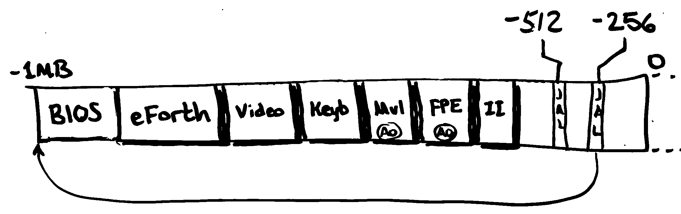
For example, the following figure represents one possible layout of components in a 1MB firmware image. The components listed could have been built with the following commands:
# Create image containing desired payload modules.

cat bios.module eforth.module \
    video.module keyb.module  \
    mul.module fpe.module II.module > firmware-image

# Make sure it fits in a 1MB ROM image.

truncate --size=1048576 firmware-image

# Make sure cold-boot vectors and modular firmware image is embedded.

dd if=modules.module of=firmware-image bs=512 seek=1920 count=128
Some discipline is required to successfully write firmware modules; however, the extra burden on the developer is fairly small. For such a system to work, the following must hold true:
- All software is written to be position-independent.
- Every module needs to start with a small header.
- The firmware contains procedures to dynamically discover and initialize modules as they’re needed.
- The firmware also needs a way to initialize certain modules before they’re actually needed.
With these requirements met, it is possible for even web-based applications hosted on low-powered virtual machines to offer customized firmware images for immediate download without having dependencies on expensive build environments or dependency graph information. The images can be synthesized on-demand for the user’s device(s) on an as-needed basis, given only a selection of components appropriate for the user’s needs.
I discuss each of these requirements in greater detail below.
Requirements
All software is written to be position-independent. A given set of modules should be able to be combined in any order and still be expected to work. Software is written in a modular manner: all modules are self-contained, statically linked, and any linkage required between modules occurs dynamically at run-time through jump-tables or data structures referenced by CPU registers. This enables software components to be written with the most simplistic of development tools.
To acquire a reference to a module in the first place, a well-known procedure is required to resolve the name to a module reference. (This will be discussed in the third requirement description, below.) The RISC-V instruction set is position-independent by default, which makes satisfying both of these requirements unusually easy.
Every module needs to start with a small header that identifies the module by name, and locates where to find subsequent modules. As of this writing, the header looks like this:
dword   MatchWord
byte    "ModuleName      "
hword   ModuleDataSize
hword   ModuleFlags
hword   DisplacementToJumpTable
hword   DisplacementToNextModule    ; 32 bytes
The MatchWord field must begin on an 8-byte boundary,
which must also be the very first 64-bit word of the module.
The value of MatchWord currently must equal $05ADC0DEFEEDC0DE.
This sequence of bytes is statistically improbable to appear in legitimate code or static data,
and therefore serves as a nice tag indicating the presence of a module.
The ModuleName field consists of up to 16 ASCII characters,
padded by spaces.
Some example module names are below:
byte    "executive       "
byte    "file system     "
byte    "gpio            "
byte    "IllegalInstHndlr"
The fixed-length text field was selected because
it requires only two bne or beq instructions to test for (in)equality,
saving the firmware implementor the burden of a general-purpose strcmp() function.
Additionally, the 16-byte field width
provides suitable descriptive power without worrying about name collisions in the general case.
If collisions becomes a problem,
the field is perfectly sized for transitioning to a UUID-based identifier
without breaking previously written software.
The ModuleDataSize field indicates to the firmware how much memory this module needs to maintain its state.
It will be described in greater detail later.
The ModuleFlags field only has one bit defined in this proposal:
bit 0 is the PREOPEN bit.
All other bits must be written as zero,
and ignored upon read, to ensure compatibility with future revisions of this protocol.
The meaning of the PREOPEN bit will be discussed later.
The DisplacementToJumpTable field contains a byte displacement relative to the MatchWord field.
This reference tells the firmware where to find this module’s jump table.
Each module is required to implement a minimum of four jump table entry points:
jal     x0, Init            ; The very first jump table entry
jal     x0, Open
jal     x0, Close
jal     x0, Expunge
; Module-specific entry-points follow.
The Init procedure is responsible for performing the one-time, global initialization of the module.
The Open procedure is invoked whenever the module is opened by a client.
The Close procedure is invoked whenever the module is closed by a client.
The Expunge procedure is called when a module should perform global shut-down procedures.
Note that both Close and Expunge cannot be allowed to fail, while Init and Open can.
How these entry points and procedures are used
will be discussed later.
The DisplacementToNextModule field contains a byte displacement relative to the MatchWord field.
This allows the firmware looking for modules
to find the next module in the firmware image, assuming one exists.
NOTE: this field must never equal zero, or simplistic system firmware images may end up in an infinite loop.
The firmware contains procedures to dynamically discover and initialize modules as they’re needed.
The most important procedure is OpenModule,
which is responsible for invoking the Open entry point of the named module.
(I’ll discuss the protocol between OpenModule and the standard entry points listed above, later.)
A typical invocation looks like this:
                align   8
_execName:      byte    "executive       "      ; Remember, pad to 16 places
_openExec:      addi    sp, sp, -8
                sd      ra, 0(sp)

_oeReference:   auipc   a1, 0                   ; A1 -> name of module to open
                addi    a1, a1, _execName - _oeReference
                ld      a0, ModulesBase(x0)     ; A0 -> module manager's data
                ld      a2, 0(a0)               ; A2 -> jump table for module manager
                jalr    ra, EP_OpenModule(a2)

                ld      ra, 0(sp)
                addi    sp, sp, 8
                jalr    x0, 0(ra)
If the call succeeds, the a0 register will point to the opened module’s instance structure in memory,
which is completely opaque to the caller
with the sole exception that offset zero of that structure refers to the module’s jump table.
This is why the example first loads a0 with the contents of the pointer at ModulesBase(x0),
and then obtains the modules facility’s jump table by setting a2 to the contents of 0(a0).
As can be seen, the API covering modules is itself a module.
If the named module failed to open for any reason, a0 will equal zero.
The firmware also needs a way to locate and initialize certain modules before they’re actually needed,
such as illegal instruction handlers intended to emulate support for missing RISC-V instructions.
Normally, OpenModule will only open the named module and,
indirectly via that module’s initialization code,
all dependencies when it is required.
However, some modules may choose to implement features missing in the target processor.
For instance, the KCP53000 CPU lacks both floating point and multiply instruction set extensions.
Yet, it’s exceptionally handy to have both of these sets of instructions.
One or more named modules could implement the trap handlers required to make this happen,
but they need to be initialized before anything else runs.
Such modules have their PREOPEN flag set,
and the firmware will open them upon discovery just after the cold-boot start-up code runs.
Protocol
A module is a self-contained, statically linked binary blob with no outside dependencies requiring fixups to run. However, it almost certainly will have outside dependencies to function at run-time. How does a module reconcile these attributes?
We start with the basic operation of the OpenModule procedure,
and in particular, the case where a module has already been opened once before.
OpenModule starts by looking through a table of already-opened modules.
If the named module is found, then it invokes that module’s Open procedure via its entry points.
This gives the opened module a chance to perform relevant book-keeping.
Note that the opened module receives a pointer to its global data structure via the a0 register,
just like any other module entry point.
Through this register, the module may access global or local data structures.
If the open is successful, a0 will be non-zero;
otherwise, a0 will equal zero.
NOTE: General purpose dynamic memory management services will not generally exist,
unless a separate module has implemented such a service.
Therefore, modules should generally work with fixed-sized data structures where possible.
What happens when the named module has not been opened yet?
OpenModule will not find its name in the list of open modules,
and so falls back on performing a scan of the firmware image.
It starts at the beginning of the firmware at a well-known or calculated address,
and checks to see if the MatchWord field matches.
If so, it then compares the ModuleName field against that sought.
If there is a successful match,
OpenModule will take the following rough steps:
- Determine the module’s data requirements by reading the ModuleDataSize field.
- Allocate 8 + ModuleDataSize bytes of memory from the Boot Data Area (BDA). This will become the Module Data Area (MDA).
- Compute the absolute address of the module’s jump table, and set offset 0 of the MDA to point to it.
- Invoke the
Initprocedure of the module, passing the MDA in registera0. This procedure is intended to initialize the global state of the MDA as given. Remember that this may involve recursively opening dependent libraries! - If the procedure returned with a successful outcome, store the MDA in a list of open modules.
- Open the module per the procedure discussed above.
If the name does not match,
or if the attempt to initialize the candidate module fails,
the address of the next module header is calculated by summing the current header’s address
and its DisplacementToNextModule field.
This process repeats for as long as headers exist (as long as the MatchWord is correct).
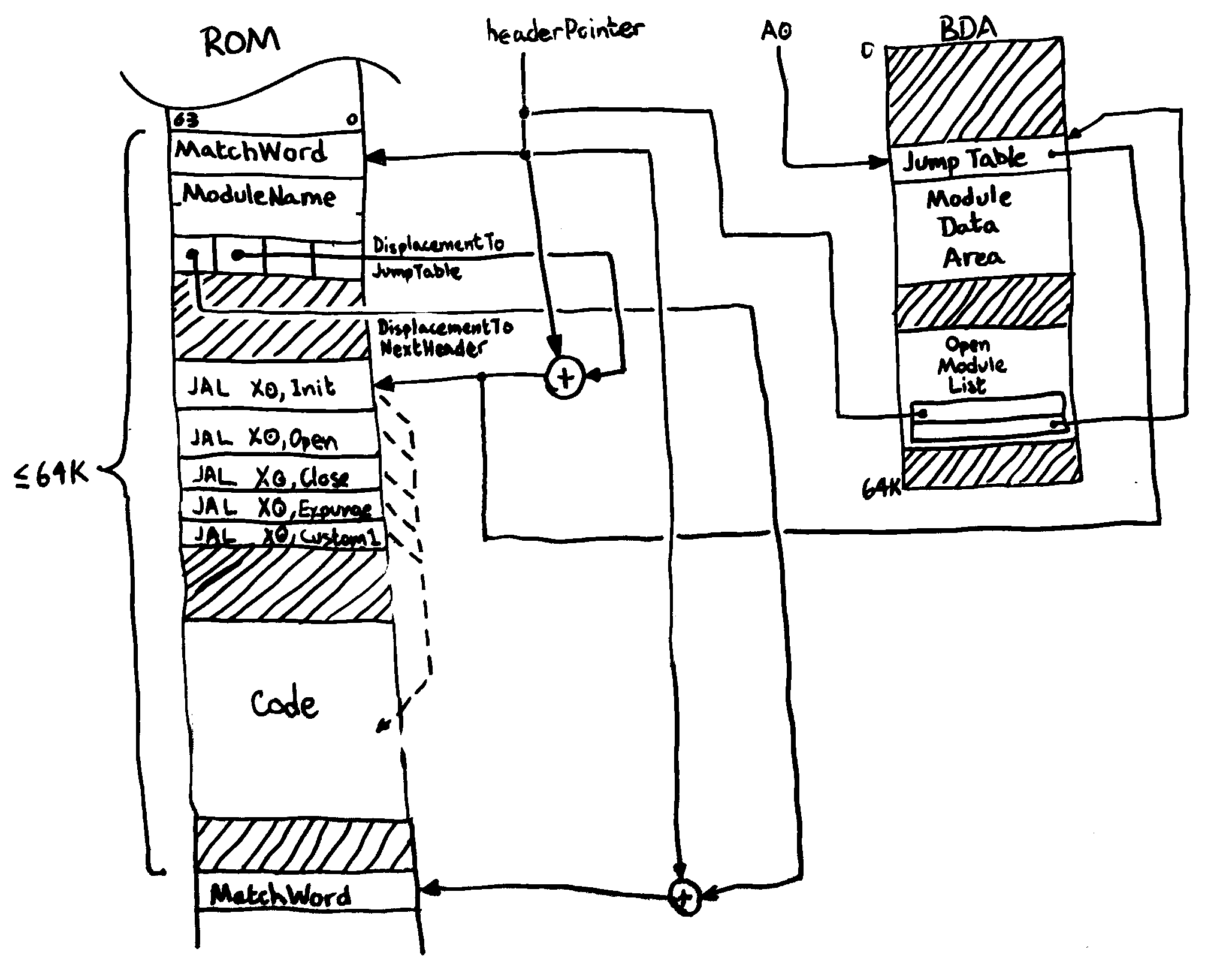
The illustration below shows the relationships of the various data structures involved. Embedded in the ROM image, you’ll find the module headers prefixing each module. This header allows the firmware scanner to quickly locate both the module’s name, its jump table, and where to find the next module. If the module is found to be a candidate, the MDA is constructed for the module to use. Since it’s very inconvenient to pass around two or more pointers when referring to one object, the head of the MDA points back to the jump table. Finally, an entry is made in the open module table, a data structure maintained only by the firmware scanner, which binds the MDA to the corresponding module’s header. This binding allows the scanner a way to access the module’s name given its MDA.
Example Module Listing
The software listing below provides what I believe qualifies as a complete module.
This module has dependencies on two other modules, dep.module.1 and dep.module.2.
We expose four functions for clients to call, two of which make calls into the dependencies.
The other two reset a counter and increments a counter, respectively.
The first half of the example comprises the required boilerplate to make the module work in the modular firmware ecosystem. The module-specific functionality will start afterwards.
                include "modules.inc"           ; Include EP_OpenModule, etc.
                include "dep1.inc"              ; EP_Fn1
                include "dep2.inc"              ; EP_Fn2

; These equations defines our MDA's structure.  Remember that
; offset 0 is reserved for the jump table pointer, which we don't
; have to worry about.

MDA_Ctr         = 8
MDA_Dep1Base    = 16
MDA_Dep2Base    = 24
MDA_sizeof      = MDA_Dep2Base

; Declare our module header.  The MatchWord *MUST* be the first
; eight bytes of the emitted binary image.

                align 8
MatchWord:      dword   $05ADC0DEFEEDC0DE       ; MatchWord.
                byte    "example.module  "      ; Our module's name.
                hword   MDA_sizeof              ; Counter value + refs to dependencies.
                hword   0                       ; No flags of interest.
                hword   JumpTab - MatchWord     ; Locate our jump table.
                hword   ModuleEnd - MatchWord   ; Locate next module if it existed.

; Our jump table.  These must include the standard boilerplate
; functions.

JumpTab:        jal     x0, Init
                jal     x0, Open
                jal     x0, Close
                jal     x0, Expunge
                jal     x0, SetCtr
                jal     x0, IncCtr
                jal     x0, DepFn1
                jal     x0, DepFn2

; --- Init
;
; This procedure attempts to initialize the MDA for the module.
; Part of this involves accessing any dependencies this module might have.
; Also, for hardware drivers, you should poll hardware to make sure it
; actually exists, if you can.
;
; Entry:
;       A0 ->   module's MDA (allocated for you)
;
; Exit:
;       A0 =    0 if something went wrong;
;               non-zero if successfully initialized.

                align   8

Dep1Name:       byte    "dep.module.1    "
Dep2Name:       byte    "dep.module.2    "

Init:           addi    sp, sp, -16
                sd      ra, 0(sp)
                sd      s0, 8(sp)

                addi    s0, a0, 0               ; Preserve our MDA for future use
                sd      x0, MDA_CTR(a0)         ; Default our counter to zero.

                ; Try to open the first dependency here.

                ld      a0, ModuleBase(x0)      ; A0 -> Module manager's MDA
i0:             auipc   a1, 0                   ; A1 -> dependency 1 name
                addi    a1, a1, Dep1Name-i0
                ld      t0, 0(a0)               ; T0 -> Module manager's jump table
                jalr    ra, EP_OpenModule(t0)   ; Call OpenModule
                beq     a0, x0, noDep1
                sd      a0, MDA_Dep1Base(s0)    ; Store reference for later.

                ; Try to open the second dependency here.
                ; This is essentially the same block of code.

                ld      a0, ModuleBase(x0)
i1:             auipc   a1, 0
                addi    a1, a1, Dep2Name-i1
                ld      t0, 0(a0)
                jalr    ra, EP_OpenModule(t0)
                beq     a0, x0, noDep2
                sd      a0, MDA_Dep2Base(s0)

                ; If we fall through here, a0 != 0, thus indicating a successful
                ; initialization.

initExit:       ld      s0, 8(sp)               ; We don't need S0 anymore.
                ld      ra, 0(sp)
                addi    sp, sp, 8
                jalr    x0, 0(ra)

                ; If we're here, one module dependency is already open,
                ; but something went wrong during subsequent steps.
                ; We need to roll back that change, so we close it again.

noDep2:         ld      a0, ModuleBase(x0)
                ld      a1, MDA_Dep1Base(s0)
                ld      t0, 0(a0)
                jalr    ra, EP_CloseModule(t0)

                ; If end up here from the guts of Init, then we couldn't even
                ; open our first dependency.  Just yield an error and exit.
                ; We could also have fallen through from other failure clean-ups.

noDep1:         addi    a0, x0, 0
                jal     x0, initExit

; --- Expunge
;
; This procedure is used to undo any reversible configurations performed by
; the Init procedure.  We're in ROM, and we predate any running operating
; system, so we don't have much to do.  In our case, we just close our
; libraries.
;
; NOTE: This example shows that you can safely cache jump table references in
; registers if you'd prefer.  Useful for when you have to make calls in rapid
; succession.
;
; Entry:
;       A0 ->   Module's MDA
;
; Exit:
;

Expunge:        addi    sp, sp, -24
                sd      ra, 0(sp)
                sd      s0, 8(sp)
                sd      s1, 16(sp)

                addi    s0, a0, 0                       ; Close dependency 2 first.
                ld      a0, ModuleBase(x0)
                ld      s1, 0(a0)
                ld      a1, MDA_Dep2Base(s0)
                jalr    ra, EP_CloseModule(s1)

                ld      a0, ModuleBase(x0)              ; Close dependency 1 next.
                ld      a1, MDA_Dep1Base(a0)
                jalr    ra, EP_CloseModule(s1)

                ld      s1, 16(sp)
                ld      s0, 8(sp)
                ld      ra, 0(sp)
                addi    sp, sp, 16
                jalr    x0, 0(ra)

; --- Open
;
; We really don't have any per-open bookkeeping to maintain, so we just
; blindly return a successful result.  This is trivially done, since
; A0 != 0 upon entry.
;
; Entry:
;       A0 ->   Module's MDA
;
; Exit:
;       A0 =    0 if open failed; non-zero otherwise.
;

Open:           jalr    x0, 0(ra)

; --- Close
;
; This rolls back any state changes made by the corresponding call to
; Open.  We have nothing to do.
;
; Entry:
;       A0 ->   Module's MDA
;
; Exit:
;

Close:          jalr    x0, 0(ra)

; --- SetCtr
;
; This function allows us to set our counter to an arbitrary value.
;
; Entry:
;       A0 ->   Module's MDA
;       A1 =    New counter value
;
; Exit:
;       A0 =    Previous counter value

SetCtr:         addi    t0, a0, 0
                ld      a0, MDA_Ctr(a0)         ; A0 = old value of counter
                sd      a1, MDA_Ctr(t0)         ; Set new value.
                jalr    x0, 0(ra)

; --- IncCtr
;
; This function allows us to increment our counter.
;
; Entry:
;       A0 ->   Module's MDA
;
; Exit:
;       A0 =    New counter value

IncCtr:         addi    t0, a0, 0
                ld      a0, MDA_Ctr(a0)
                addi    a0, a0, 1
                sd      a0, MDA_Ctr(t0)
                jalr    x0, 0(ra)

; --- DepFn1
; --- DepFn2
;
; These two functions call into our dependencies.  This illustrates
; how to provide the required dynamic linkage between modules.
;
; Entry:
;       A0 ->   Module's MDA
;       ...
;
; Exit:
;       ...

DepFn1:         ld      a0, MDA_Dep1Base(a0)    ; A0 -> dependency's MDA
                ld      t0, 0(a0)               ; T0 -> jump table for dependency
                jalr    x0, EP_Fn1(t0)          ; Call the function and return

DepFn2:         ld      a0, MDA_Dep2Base(a0)
                ld      t0, 0(a0)
                jalr    x0, EP_Fn2(t0)

; This symbol MUST be the last in the listing in order to properly calculate
; the DisplacementToNextModule field in the module header.

ModuleEnd:
Limitations
There are several limitations with the described approach towards supporting modular firmware. First and perhaps most obvious from inspecting the module’s header is the 64KiB limitation for a single module. Second, the ABI depends on a jump table, rather than a vector table. Third, C compilers must be configured to produce position-independent code, which means the creation of a global object table (GOT), which is not easily made compatible with the MDA.
The 64KiB is mostly an issue when attempting to write modules in a language such as C or Oberon. One work-around is to concentrate on keeping your modules as simple as possible. Modules are intended to be composed to form more complex functionality; large-scale services, such as providing a complete filesystem or network stack, exceeds the intended use-case. Another work-around is to simply redefine the header to support larger ModuleDataSize and DisplacementToNextModule fields.
The use of jump tables impedes direct invocation of module services from a higher level language such as C or Oberon. Neither C nor Oberon provide convenient syntactic support for expressing the concept of “this procedure is at offset 16 from this variable.” The closest you can approximate is to manually perform these calculations yourself via pointers to functions, like so:
extern ModuleBase *pModuleBase;

int (*pSetCtr)(ModuleBase *, int);
int (*pIncCtr)(ModuleBase *);
int (*pDepFn1)(ModuleBase *, ...);
int (*pDepFn2)(ModuleBase *, ...);

base = OpenModule(*pModuleBase, "example.module  ");
pSetCtr = *base + 16;
pIncCtr = *base + 20;
pDepFn1 = *base + 24;
pDepFn2 = *base + 28;
Finally, it’s unclear how to convince a C compiler to place its global object table into a module’s MDA, which raises interesting chicken and egg problems with module bring-up when placed in a ROM environment. C always assumes code is running in RAM, and to support this mode of operation, a statically compiled GOT will need to be copied into RAM. On the RISC-V platform, this can be most problematic, since in the case of the Kestrel-3 in particular, ROM and RAM are separated by more than 60-bits worth of address space! GCC and LLVM, compilers which currently support the RISC-V ISA, are not built to handle this case.
Prior Art
The module concept as described here traces its roots back to the library mechanism found in Commodore-Amiga’s
AmigaOS operating system.
AmigaOS has no distinct “kernel”;
while exec.library can be identified uniquely as an early microkernel design,
the remainder of the OS consists of an amorphous web of interacting modules.
Modules can take one of three forms: libraries, devices, or resources.
At the ABI level, however, the different module types unify,
and all are ultimately managed by a single set of functions:
OpenLibrary, CloseLibrary, FindLibrary, AddLibrary, and RemLibrary.
The module system described in this article, however, is not intended to form the basis for a complete operating system.
The uCLinux community provides an executable format known as bFLT. bFLT has a number of attributes in common with the module system described. For instance, the bFLT format allows you to concatenate a number of binaries in series, and based on the header fields found in any given bFLT component, you can calculate where to find the next. However, bFLT is intended to contain programs, not libraries of functions. For this reason, a calling convention would be needed to more or less convert the program into a library. bFLT images also do not expose a module’s name, so that too would need to be part of the calling convention of the program. bFLT images might lend themselves very well to a COM-object-based system of modularity, such as those found in environments based on OSKit, however.
Conclusion
In the face of a potentially large set of hardware configurations for the Kestrel-3 computer design, this module system allows the firmware to load an operating system from mass media if available. The module system helps because it allows for the isolation the bootstrap procedures from the specific I/O mechanisms used. It allows this without heavy-weight tooling: an assembler that is capable of producing static binaries is sufficient. It’s also more flexible than commonly used heavyweight tooling: drivers can fail to initialize (and thus, fail to open) if appropriate I/O interfaces are not supported, which can be detected and acted upon in an intelligent manner. Simple filesystems, now isolated from their I/O dependencies, can fail if required signatures on the mass media volume are missing or corrupt. Which drivers and which filesystems are used will be up to the firmware’s user, who selects pieces “off the shelf” and assembles them together with very simple file manipulation commands. This stands in contrast with, for instance, ELF-based build environments, where binaries are linked together by the provider, not the consumer. This avoids the inevitable combinatorial explosion of configurations that need to be supported.
The module system also aids in providing an interactive programming environment if mass media or an operating system is not available. Programming environments similarly require I/O interfaces to function (keyboard and video output console drivers, mass storage, etc.), yet derive great benefits through modular isolation. The module mechanism described in this article allows this to happen in a hardware configuration independent manner. Someone can take eForth 1.0 firmware, for example, and bind it either to an RS-232 interface or to a bitmapped video display driver, simply by selecting which modules to lump together in the final binary image.
There are, of course, other possible solutions to the combinatorial support problems that widely different FPGA systems present, and they should be considered. However, I think the modular firmware approach described in this article is worthy of consideration. The implementation complexity is reasonable, even for individual programmers working with very simple tools, yet offers rewards on par with heavier-weight build environments.

Samuel A. Falvo II
Twitter: @SamuelAFalvoII
Google+: +Samuel A. Falvo II
About the Author
Software engineer by day. Amateur computer engineer by night. Founded the Kestrel Computer Project as a proof-of-concept back in 2007, with the Kestrel-1 computer built around the 65816 CPU. Since then, he's evolved the design to use a simple stack-architecture CPU with the Kestrel-2, and is now in the process of refining the design once more with a 64-bit RISC-V compatible engine in the Kestrel-3.
Samuel is or was:
- a Forth, Oberon, J, and Go enthusiast.
- an amateur radio operator (KC5TJA/6).
- an amateur photographer.
- an intermittent amateur astronomer, astrophotographer.
- a student of two martial arts (don't worry; he's still rather poor at them, so you're still safe around him. Or not, depending on your point of view).
- a former semiconductor verification technician for the HIPP-II and HIPP-III line of Hifn, Inc. line-speed compression and encryption VLSI chips.
- the co-founder of Armored Internet, a small yet well-respected Internet Service Provider in Carlsbad, CA that, sadly, had to close its doors after three years.
- the author of GCOM, an open-source, Microsoft COM-compatible component runtime environment. I also made a proprietary fork named Andromeda for Amiga, Inc.'s AmigaDE software stack. It eventually influenced AmigaOS 4.0's bizarre "interface" concept for exec libraries. (Please accept my apologies for this architectural blemish; I warned them not to use it in AmigaOS, but they didn't listen.)
- the former maintainer and contributor to Gophercloud.
- a contributor to Mimic.
Samuel seeks inspirations in many things, but is particularly moved by those things which moved or enabled him as a child. These include all things Commodore, Amiga, Atari, and all those old Radio-Electronics magazines he used to read as a kid.
Today, he lives in the San Francisco Bay Area with his beautiful wife, Steph, and four cats; 13, 6.5, Tabitha, and Panther.